#Hardware notes
Assembly reference for Tersler. Section numbers refer to the ASUS Z10PA-U8 user guide in reference/.
#Slot placement
top of board (CPU, DIMMs)
  MIO1   audio only
  PCIE6  x16 Gen3  ← P100 #1  (its cooler covers PCIE5)
  PCIE5  x8        (leave empty, else PCIE6 drops to x8)
  PCIE4  x16 Gen3  ← P100 #2  (its cooler covers PCIE3)
  PCIE3  x8        (leave empty, else PCIE4 drops to x8)
  PCI2   PCI
  PCIE1  x8 slot, x4 Gen2 via PCH (free: NVMe adapter later?)
bottom
Both x16 slots hang off CPU1, so P2P between the cards stays on one root complex. The cards sit directly next to each other with no gap. That is fine, because the airflow runs lengthwise through the fins.
#RAM placement
- The manual says to always start with slot A1 (§2.4).
- Now: one 16 GB stick (SK hynix HMA42GR7AFR4N-TF, DDR4-2133 RDIMM 2Rx4) in A1.
- Upgrade (2026-11-10): 3 more of the same 16 GB stick, 64 GB in total (62 GB usable, ECC on, no EDAC errors).
- Channel D is dead on this board/CPU: every combination with a stick in D1 or D2 stops POST at
0x55with 4 long beeps (memory not usable). A1+B1 and A1+C1 boot. One-per-channel (A1/B1/C1/D1) stops at0xB7. The CPU socket looked fine. The CPU is missing a few parts on its underside (not yet known whether they matter). Next step: a replacement E5-2690 v3 (~€12) shows whether it is the CPU or the board. - Now: A1, B1, C1, C2. Three channels, but C has two sticks, so everything runs at 1866 MT/s.
- Bandwidth is the same as with A1/A2/C1/C2: read 28.4 GB/s on every 4 GB chunk of 48 GB, triad 20.2 GB/s. That is about two channels' worth (2 × 1866 MT/s = 29.9 GB/s theoretical). The likely reason: memory is interleaved across the CPU's two memory controllers (A+B and C+D), so the controller with only channel C sets the pace. Without channel D no layout gets more. With D: 4 × 2133 MT/s = 68 GB/s theoretical.
- Doesn't matter for models that fit in VRAM. Limits decode for MoE models with experts in system RAM (Flash-Next, tandem.cpp, Strata).
- Check after boot:
sudo dmidecode -t memory | grep -E 'Locator|Size'and the EDAC entries in/sys/devices/system/edac/mc/(hereHa#0_Chan#0,Ha#0_Chan#1,Ha#1_Chan#0×2).
#BIOS settings (set before installing the GPUs)
| Setting | Where | Value |
|---|---|---|
| Above 4G Decoding | Advanced → PCI Subsystem Settings (§4.4.8) | Enabled |
| Intel VT-d | IntelRCSetup → IIO Configuration (§4.5.5) | Enabled (default); OS uses iommu=pt |
| Primary display | onboard VGA | keep the onboard ASPEED |
| PCIE4 / PCIE6 Option ROM | IIO → PCIE Slot Option ROM | Disabled may speed up POST |
| CPU fan header | CPU_FAN1 | cooler fan |
#If the board still won't boot with the cards (BAR1 problem)
Use the fallback from the reference recipe: switch the cards to graphics mode (BAR1 16 GB → 256 MB) with nvflash.
- Back up each card first:
nvflash --save p100_cardN_backup.rom. - Flash:
nvflash -i N --gpumode graphics. The first reboot may power-cycle three times; don't interrupt it. - The flash turns ECC off. Re-enable it with
nvidia-smi -i N -e 1, then reboot.
Only do this if Above 4G Decoding is not enough. install/install.sh does not automate it.
#Power
| Seasonic SSP-650RT cable | Goes to |
|---|---|
| 24-pin ATX | board |
| 4+4-pin CPU | board 8-pin CPU (EPS) |
| 8-pin CPU (EPS) | P100 #1, directly |
| 2× PCIe 6+2 → the card's own Y-adapter | P100 #2 |
Peak budget at 150 W per card: about 485 W, which leaves ~165 W headroom.
#Y-adapters that came with the cards
Both legs must be connected. Each leg feeds only some of the EPS plug's 12 V/GND pins; the legs aren't joined inside the adapter. With one leg the card sees dead 12 V pins and refuses to start (dmesg: NVRM: GPU ... does not have the necessary power cables connected). In this build P100 #2 runs on its Y-adapter, with both legs on the PSU's two PCIe 6+2 cables; use the full 8 pins of each 6+2 plug.
#Homemade 2× PCIe 6+2 → EPS 8-pin adapter
Not used in this build (the Y-adapters above did the job). Only needed if your cards come without adapters.
- Parts: one Goobay EPS extension (plug → socket); two of the PSU's PCIe 6+2 cables.
- Build:
- Cut off the extension's socket (female) end. Keep the plug (male) end, which goes into the P100.
- Join the plug's four 12 V wires to the 12 V wires of both PCIe cables, and its four ground wires to the PCIe ground wires. Leave out the PCIe sense pins (keep the 6+2 "+2" part unused).
- Verify before connecting the card:
- Don't trust wire colours alone. Compare against the PSU's native EPS plug that powers P100 #1: with the PSU on (paperclip PS_ON or a running board), the homemade plug must show +12 V and GND on exactly the same pin positions as the native one.
- Check that there is no short between 12 V and GND, and that every 12 V pin shows continuity.
- Never plug a PCIe 8-pin into a P100. EPS and PCIe 8-pin have roughly mirrored pinouts.
- Current: 150 W / 12 V ≈ 12.5 A, about 3 A per wire across four 12 V wires. Even 250 W stays at ~5 A per wire with 18 AWG.
#Cooling
#Front duct (current plan: tower case)
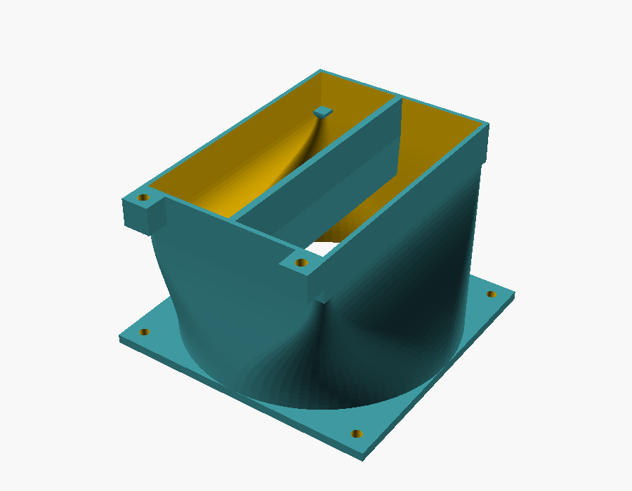
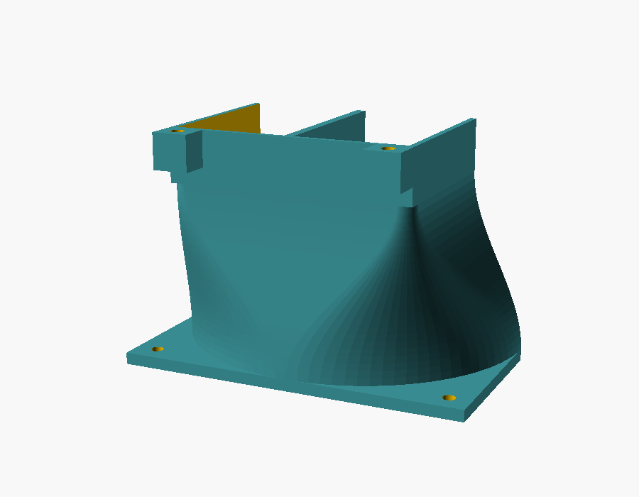
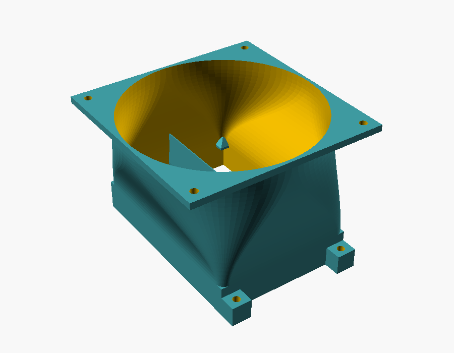
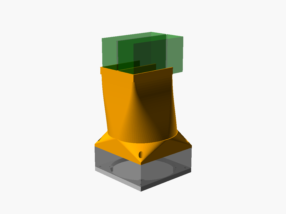
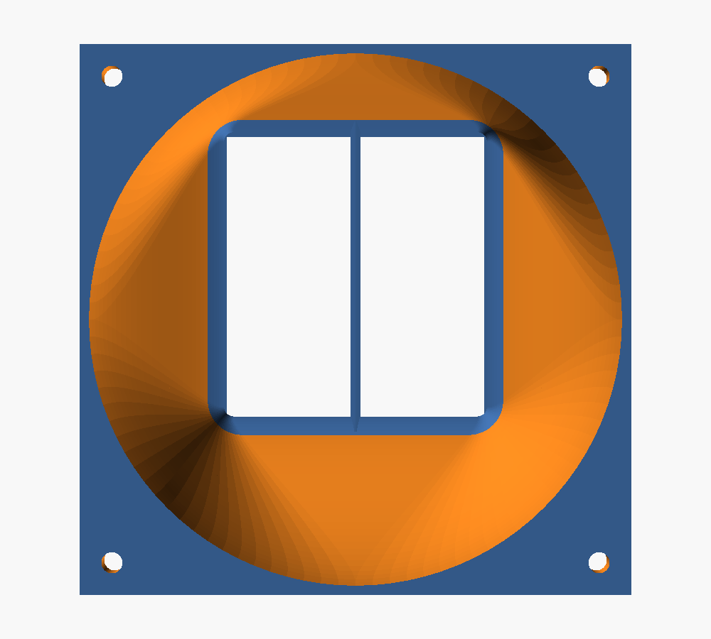
The board sits in a tower case after all. The card tails point at the case front, ~180 mm from the inner front wall, roughly level with the case's 92 mm front fan. shroud/p100_front_duct.scad replaces that fan:
case wall | wall plate (8) | Arctic 120x38 | duct (132) | card tails- Wall plate: screws onto the 92 mm fan holes (82.5 mm) from outside. Four M4 nuts sit in traps on its wall side.
- Fan and duct: fixed with 4× M4×50 bolts from inside the duct flange, through the fan, into the plate's nuts.
- Duct end: stops at the card tails; seal the ~2 mm gap with foam tape. Side fingers, a bottom finger and the gap blocker locate it on the cards.
- Plugs: the EPS plugs sit on the tail faces at the cards' top edge, and the duct's top wall stays below them (
plug_zone). Route the cables upwards, away from the board. - Printing: card end down, no supports.
- Still to measure before printing:
plug_zone- the fan/card offsets
x_off/y_off - the hole centre
case_dx/case_dy - whether 120 × 120 mm of free wall area exists there
#Shroud placement (original design, open frame)
This assumes an open-frame build (no case). The shroud slides onto the cards' tail ends, the end opposite the slot brackets. In a normal case that end would point into the case, toward the front. The fan blows into the fins there, and the air exits through the slot-bracket vents.
- The cards (267 mm) are longer than the board is deep along them (244 mm), so their tails stick out past the board's front edge: roughly 20–30 mm, estimated from the board photo, not measured. Shroud plus fan (~120 mm) sit entirely beyond that edge, so no board components are in the way.
- In a case this would need ~120 mm of free space in front of the card tails; most cases can't do that.
- Support the fan. It cantilevers ~120 mm off the card tails; use the shroud's two mounting tabs and a strut or zip ties to the frame.
- The air exits through the slot-bracket vents. Keep ~5 cm free behind the brackets.
#Fan
- Arctic S12038-4K, 120 × 38 mm. Measured hole spacing 106 mm centre-to-centre, holes 4.5 mm. Mount it with M4 × 45 bolts and nuts (4 mm flange + 38 mm fan).
- Estimated airflow need: 300 W at ΔT 15 °C ≈ 60 m³/h (35 CFM) through the fins.
- Speed control:
- The board regulates its fan headers on CPU temperature, so GPU heat is invisible to it.
scripts/fan-control.shdrives a PWM header fromnvidia-smitemperatures, if the board's PWM is exposed in Linux. Check withscripts/fan-control.sh --discover.- Otherwise run the fan at a fixed speed set in the BIOS.
#Board fan chip (found 2026-11-06)
- The fan headers sit on a Nuvoton NCT7904D (I²C 0x2d, driver
nct7904, loaded via/etc/modules-load.d/tersler-sensors.conf). There is no IPMI/BMC. The NCT6779D Super-I/O (nct6775) has no fans connected. - PWM outputs:
pwm1→fan1(CPU cooler),pwm2→fan5(GPU intake fan,FAN_PWM=pwm2);pwm3/pwm4drive nothing connected.fan7is the 3-pin rear case fan, not controllable. pwmN_enable: 2 = the chip's own automatic curve (default), 1 = manual.
#Fan sweep (2026-11-07, cardboard duct, ~140 W per card, lean_bench load)
| pwm | rpm | GPU 0 | GPU 1 | gap |
|---|---|---|---|---|
| 190 | 2840 | 56 °C | 64 °C | 8 K |
| 160 | 2530 | 60 °C | 69 °C | 9 K |
| 130 | — | ~66 °C | 77 °C, still rising | ≥11 K |
- The pwm 130 step was aborted: 77 °C is too close to the cards' limits (slowdown 82 °C, shutdown 85 °C).
- The gap grows as the airflow drops, so GPU 1 most likely gets less air from the duct; uneven paste would keep a constant gap.
- The hotter card sets the fan speed, so balancing the duct is the first lever for noise.
#Targets
- Below ~75 °C sustained at 150 W.
- An unducted fan in the reference build reached 79 °C in 35 s.
#Measure on arrival (needed for the shroud)
-
card_h: tail face height (PCB edge to top of the cooler cover) -
card_t: cooler cover thickness at the tail -
slot_pitch: centre-to-centre of the installed cards (nominal 40.64 mm) - Gap between the coolers (nominal 3.6 mm; needs ≥ ~1.5 mm for the blocker)
- Anything on the tail ends: screw holes, retention bracket, tabs
Duct renders